An automatic tool changer is only as dependable as the information connecting the physical cutting tool to the program that requests it. Your CAM workflow is ready when one cutter can be traced consistently from its vendor specification and measured tool assembly through the CAM library, NC output, machine tool table, and loaded rack position.
Automation does not repair mismatched names, numbers, dimensions, offsets, or rack assignments. It can instead make a mismatch repeatable at machine speed, so treat readiness as a chain-of-custody problem before treating it as a feature.
Map one cutter through the entire digital-to-physical chain
Start with one real cutter—not a full library. Choose a tool you use in a representative multi-tool job, such as a clearing end mill, V-bit, drill, or profile cutter. Then create a record that follows that exact physical assembly through seven linked references.
The word “same” matters. Two cutters can have similar descriptions while differing in diameter, flute length, overall length, shank size, coating, holder projection, or cutting purpose. A matching file name does not prove that the tool in the rack matches the tool defined in CAM.
Do not fill a blank field with an assumption. “Probably the same bit” is a stop condition. So is a tool number that differs between the CAM file, posted program, machine record, and rack label.
Avid CNC’s ATC documentation describes the dependency directly for its own system: CAM and G-code tool numbers must match the physical rack bins, and a mismatch can damage the workpiece. The exact bin rules, controls, and setup methods are Avid-specific, but the underlying requirement applies to any automated change workflow: the software request and the physical loaded tool must agree.
Build a machine-specific tool library
A tool library is a structured source of information about cutting tools. It should not be a folder of generic names copied from a catalog. For ATC work, separate information that comes from the tool vendor from information that belongs to your measured, prepared tool assembly and your specific machine.
Autodesk Fusion documentation describes its Tool Library as a place to manage milling tools, holders, tool properties, libraries, and cutting-data presets. Fusion can be useful for organizing these records, but use of a tool-library feature does not validate the information entered or establish that a particular machine supports the resulting output.
A practical library separates four data groups:
-
Vendor tool data: The tool’s manufacturer identification, basic geometry, material or coating information where documented, and any tool-specific limitations.
-
Measured assembly data: The actual cutter and toolholder combination being loaded. A cutting tool installed farther out from a holder is not the same physical assembly as that cutter installed at a different projection.
-
Cutting-data presets: Machine-, material-, workholding-, and operation-dependent values. These are not universal properties of the bit, and they should not be copied from an unrelated machine or project without review.
-
Machine-specific identifiers: The tool number, assigned rack or magazine position, tool-length reference method, and any controller-side identifiers required by the documented workflow.
Avoid using a generic entry such as “1/4-inch end mill” for multiple physical cutters that are not genuinely interchangeable. If a cutter is replaced, remeasured, moved to another toolholder, or loaded into a different rack station, review each affected link in the record.
Autodesk also documents that Fusion allows a user to set the tool number used for a tool change in the tool record. That number is only an instruction in the CAM data until the selected post processor and machine-side setup interpret it correctly.
Make tool numbers and rack positions agree
Tool numbers are the handoff point between the planned job and the machine’s physical tool inventory. A program may request a tool number, but the machine can only change to the tool that is actually prepared, identified, and loaded where the documented machine workflow expects it.
Before running a multi-tool job, compare four records side by side:
-
The tool number in the CAM operation.
-
The tool number shown in the posted NC output or its associated tool list.
-
The corresponding tool number in the machine’s tool table or documented controller workflow.
-
The physical toolholder and cutting tool loaded in the relevant rack or magazine station.
Avid’s ATC documentation uses a direct relationship between CAM/G-code tool numbers and physical rack bins for its system. Its documentation also warns users to ensure the correct tool is loaded in each bin before operating. Do not copy that brand’s particular numbering convention to another machine. Instead, use it as a reminder to obtain the manufacturer’s own mapping rules.
A useful pre-run practice is to label both the physical holder and the rack position using the same machine-specific identifier used in the approved workflow. If a tool is moved, replaced, or reassembled, revise the record before the next job. A durable label does not prove the contents are correct; it makes the later identity check possible.
Stop and clarify the setup if any of these conditions exist:
-
The CAM tool number does not match the posted program’s requested number.
-
The posted program cannot be inspected for the planned tool sequence.
-
The machine-side tool table or ATC mapping is undocumented or cannot be verified.
-
The physical cutter differs from the cutter represented in the CAM record.
-
The rack contains an empty, unmarked, substituted, or uncertain tool assembly.
-
A tool has been moved but the CAM, machine, or rack record was not updated.
Verify the machine definition and post path
A post processor translates the CAM operation into machine-specific NC output. The CAM tool library describes the intended cutter; the post processor determines whether, and how, the program expresses tool-change requests for a particular control environment.

That distinction is essential for ATC readiness. A valid-looking tool number in CAM does not prove the selected machine definition or post processor will produce a tool-change instruction that the machine can interpret. Likewise, a simulation can help reveal certain planning errors but cannot verify the physical holder, loaded rack position, clearance, offset status, or recovery behavior.
Before relying on automatic tool changes, confirm that the machine manufacturer documents:
-
The machine definition or setup required for multi-tool jobs
-
The supported post-processor path or approved NC-output workflow
-
How tool numbers should appear in the posted program
-
How the controller associates a requested number with a physical rack or magazine position
-
How tool-length offsets or equivalent references are established
-
How to inspect the tool list before machining
-
What to do when a requested tool is unavailable, incorrectly loaded, or not picked up correctly
-
The documented recovery procedure after an interrupted job or failed change
Do not invent G-code, commands, macro sequences, post names, menu locations, or file-format claims when the machine documentation does not provide them. The correct question is not “Can my CAM package issue a tool number?” It is “Can my selected CAM, post, control, machine tool table, and physical rack execute and verify this exact tool sequence according to the machine manufacturer’s documentation?”
Run a no-cut readiness test
Start with a powered-off identity check. Confirm that the physical tool, holder, label, intended rack position, CAM record, tool number, and posted program all represent the same assembly. Verify that the work envelope, workholding, tool length, fixture height, and magazine area are suitable for the intended sequence according to the machine’s documentation.
Then use only the manufacturer-approved verification process for the specific machine. Do not invent dry-run motion, clearance values, overrides, or controller steps based on a different ATC system. Avid’s documentation illustrates why model-specific setup matters: its ATC configuration includes tool-rack details, tool-change behavior, machine-specific bin locations, and entry and exit requirements. Those controls should not be assumed for another machine.
After the approved no-cut verification, use a sacrificial first job or representative offcut rather than immediately running a high-value workpiece. Keep the first operation simple enough to inspect the expected tool sequence, cutting result, workholding, and any behavior that differs from the documented workflow.
A successful simulation or dry verification is useful evidence, but it is not a guarantee of safe machining or an accepted part. You still need active supervision, secure workholding, correct toolholding, chip and dust control, appropriate personal protective equipment, and a clear stop procedure. Automated tool changing does not authorize unattended CNC operation.
Decide whether the workflow is ready
Classify the workflow based on evidence, not confidence.
The minimum evidence is straightforward: the cutter you load must be the cutter CAM plans for, the number requested in NC output must be the number the machine recognizes, the loaded station must match the intended assignment, and the machine manufacturer must document the offset, verification, and recovery workflow.
For an exact cutter source, the TwoTrees CNC router bits collection can help you identify available bit categories. Collection membership alone does not prove that a cutter fits a specific holder, ATC rack, collet, spindle, or machine. Verify the individual product specifications and the machine’s toolholding limits before adding any cutter to an automated tool chain.
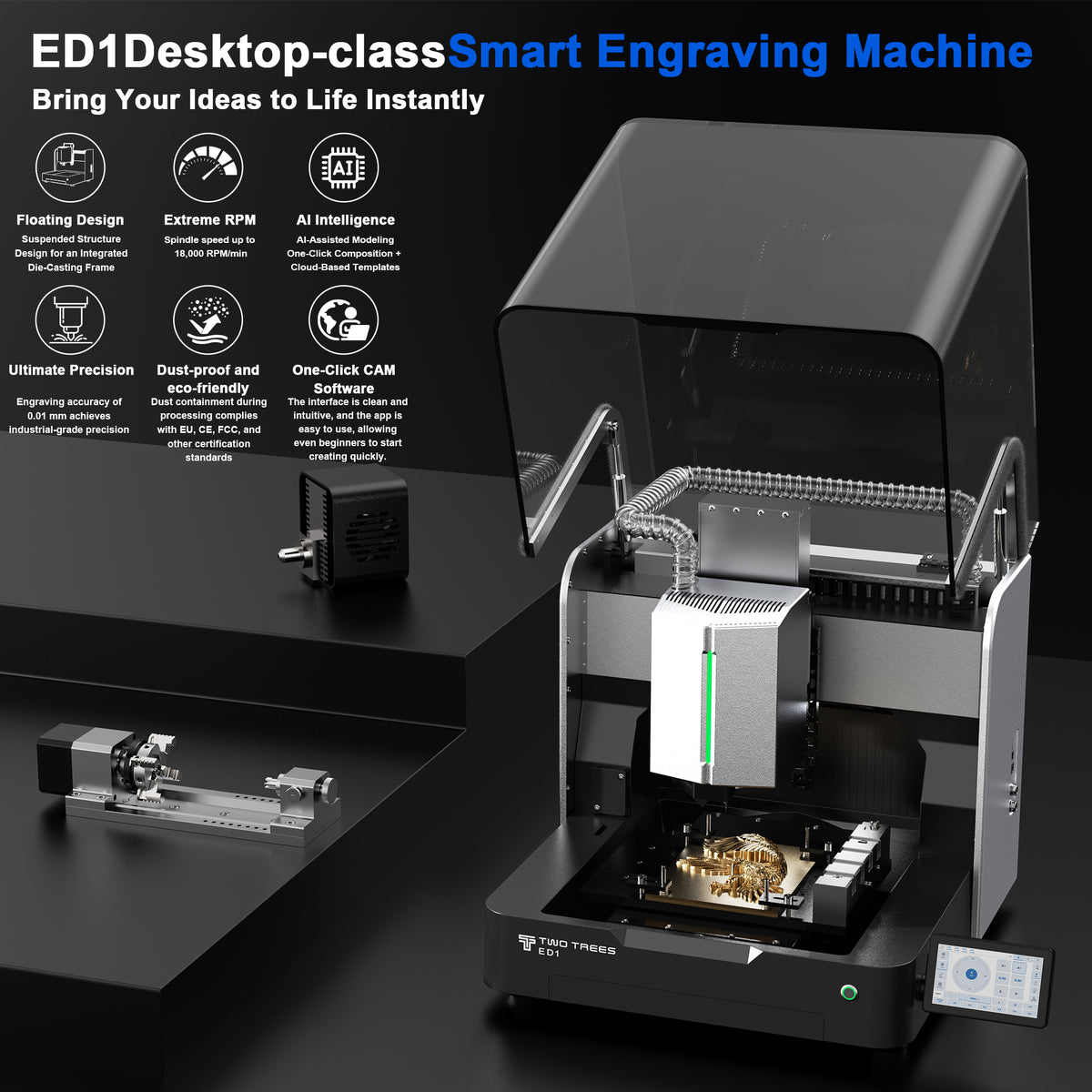
The TwoTrees ED1 enclosed desktop CNC is advertised as an enclosed desktop CNC with a fully automatic tool changer, five-tool capacity, and WeCarver CAM. Those product-page statements do not document the full tool-library, post-processor, tool-number, offset, or failed-change recovery workflow required for this audit. If you are considering ED1, ask TwoTrees for current written documentation covering the toolholder interface, tool-number mapping, supported CAM/post path, tool-length workflow, rack or magazine assignment, and recovery process before ordering.