CNC probe accuracy and repeatability answer different questions. Repeatability describes how closely repeated results agree under specified conditions. Accuracy concerns how closely a measured value agrees with the true value. A probe can produce a tight cluster of readings that are consistently displaced from the reference you intended to locate.
For a desktop maker, that distinction affects what a small number on a specification sheet actually promises. Consistent contacts are useful when relating a design to physical stock, but consistency alone does not establish a correct work origin or a finished part's tolerance. Before comparing two numbers, establish what result each describes and which conditions belong to it.
A Small Spread Can Sit in the Wrong Place
Consider a hypothetical reference at exactly X = 20.000 mm. Suppose three readings of the same feature, approached from the same direction under unchanged conditions, are 20.039, 20.040 and 20.041 mm. These are illustrative numbers, not measurements of the ED1 or any other machine, and the exact reference is a mathematical assumption.
The observed range is 20.041 − 20.039 = 0.002 mm. That describes the separation between the largest and smallest readings in this small set. Their mean is 20.040 mm, which is 0.040 mm above the assumed reference. The readings agree closely with one another while remaining displaced from the value being sought. There is no contradiction: spread and offset describe different relationships.
If you saw only the three readings, you could calculate their range but could not discover that offset. You would need a suitable reference comparison. In real measurement, the reference has its own stated value and uncertainty; it is not infinitely exact like the assumption in this example. The comparison must be capable of resolving the difference that matters to the job.
Taking the average does not remove a common displacement. Averaging the hypothetical readings gives 20.040 mm, not 20.000 mm. Repetition can reveal how results vary, but it cannot, by itself, reveal where the whole cluster should have been. Correcting an identified systematic error belongs to the approved procedure for the installed system, rather than to an offset guessed from a handful of similar readings.
The International Vocabulary of Metrology, published through the JCGM, distinguishes accuracy from precision and defines repeatability as precision under repeatability conditions. Accuracy is a qualitative concept related to both trueness and precision, not simply another name for the mean offset in the example. The practical lesson is to examine agreement with a reference as well as agreement between readings.
Read the Repeatability Statistic Before Comparing Values
The number of decimal places on a controller is not a demonstration of probing performance. A display can show small increments without establishing that the installed system can locate a feature correctly to those increments. Resolution tells you something about the indication; it does not independently establish accuracy or repeatability.
Even two repeatability figures expressed in the same units may describe different quantities. A maximum-minus-minimum range is the observed separation of the extremes in a set. Standard deviation describes dispersion differently. A value labeled “2σ” refers to twice the standard deviation in its stated context. It is not interchangeable with an observed range or a plus-or-minus maximum-error limit.
Return to the hypothetical readings: 0.002 mm is their range. Relabeling it “2-sigma accuracy” would change both the statistic and the property being described without supplying the evidence for either change. Likewise, a specification expressed using 2σ does not become a guaranteed boundary for every future result merely because the number is small.
This is why a meaningful comparison starts with the label rather than the smallest advertised value. Establish whether a figure describes a probe tip's repeated response, an installed machine's located coordinate, or a finished feature. Then establish how it was calculated. Converting units can make the units match; it cannot make different measurement questions equivalent.
One Approach Direction Does Not Describe Every Contact
Renishaw's TP8 CMM probe specification provides a useful example of careful labeling. It lists unidirectional repeatability at the stylus tip separately from pre-travel variation around the XY plane. It also states the stylus length, ball size, velocity and force conditions associated with its data. Those separate fields show why “probe accuracy” is not adequately described by pulling one number out of a specification.
Unidirectional repeatability concerns repeated behavior from one direction. A claim about variation across directions addresses another relationship. A system could behave consistently when approaching a surface from one side without that result alone establishing what happens when it approaches from a different side.
Pre-travel helps explain the distinction. It is the movement between initial contact and the trigger response. In its TP7M documentation, Renishaw explains how direction-dependent trigger behavior can contribute to pre-travel variation. That is a mechanism described for the documented CMM probe system, not a description of the ED1 accessory's internal construction.
The conditions underneath a specification therefore belong with the figure, not in a footnote to ignore. A result associated with a particular stylus and approach condition cannot automatically be extended to a different arrangement. The TP8 example demonstrates how to read the scope of a claim; its performance values and operating conditions are not settings or performance claims for a desktop CNC probe.
From Probe Response to a Located Workpiece
Workpiece location is a useful result in its own right. If the artwork and toolpaths for a small plaque are already prepared, the remaining setup question may be where the secured blank sits relative to the design's reference. The TwoTrees ED1 3D wired probe is the dedicated accessory for workpiece-origin positioning. Its relevant role is connecting that design reference to the physical setup.
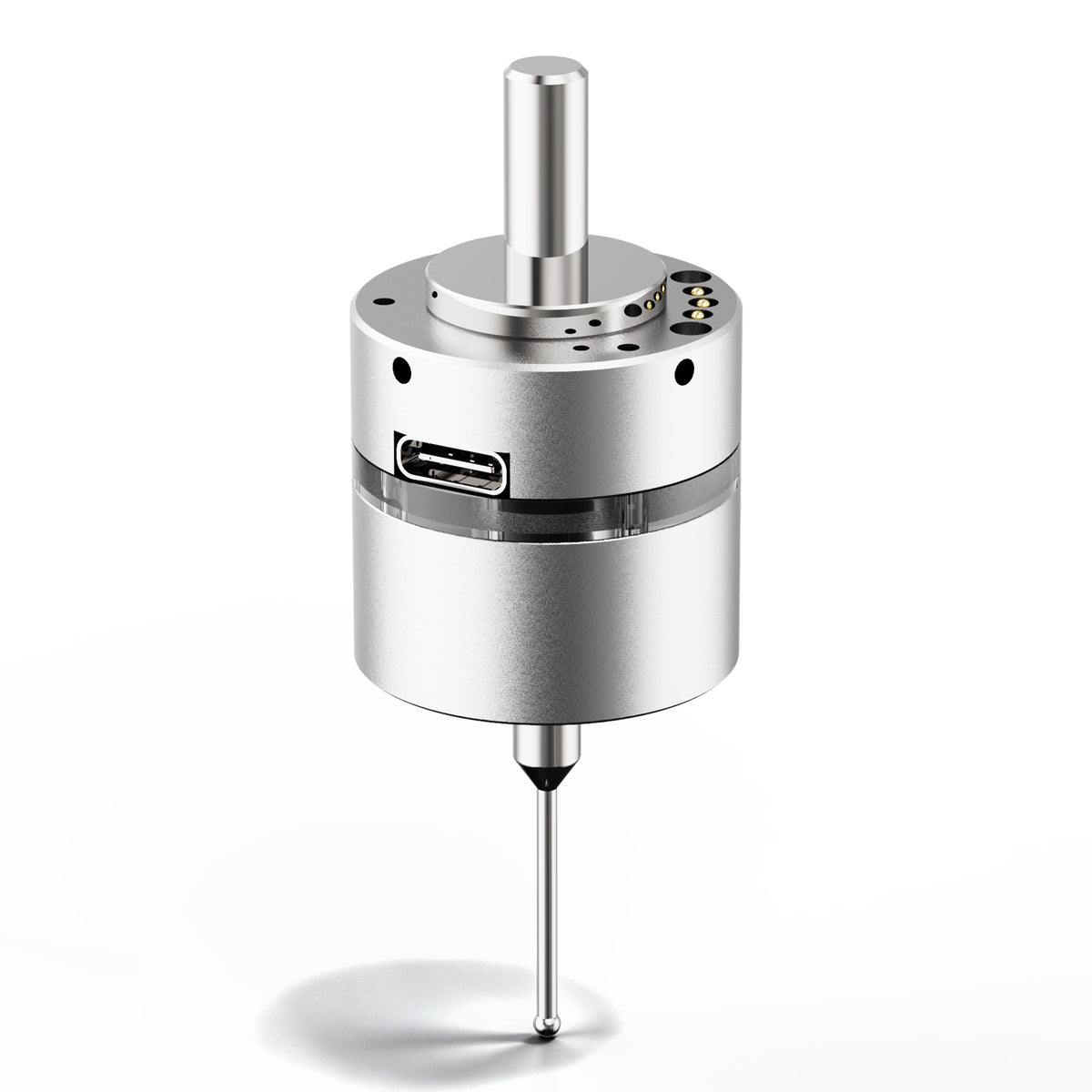
A component specification and a located workpiece reference still have different boundaries. The installed result includes the relationship among the probe, machine, selected physical feature and supported positioning method. The correct question is whether evidence describes the result you need, rather than whether an accessory's name contains “precision” or “3D.”
The VIM's repeatability conditions include the same procedure, operator, measuring system, operating conditions and location, with replication over a short period. Those conditions explain an important practical distinction: repeating a contact while the stock remains secured is not the same experiment as removing the blank and loading it again. The second situation introduces a changed setup.
Suppose the hypothetical plaque is probed several times without being disturbed. Those contacts concern the reference in that arrangement. If the maker then removes and reclamps it, a result from the earlier contacts does not establish that the new physical arrangement is identical. That does not make the probe unhelpful; locating the workpiece in its actual setup is precisely the relevant task. It means the earlier spread must not be presented as evidence of an untested reload process.
A Finished Cut Adds a Different Requirement
On the ED1 desktop CNC router, positioning the blank is one relationship within the machining workflow. A finished feature also depends on the cutting tool, machine motion, workholding, material and programmed operation. Repeated probe contacts do not apply the cutting forces or create the surface whose final dimensions will be evaluated.
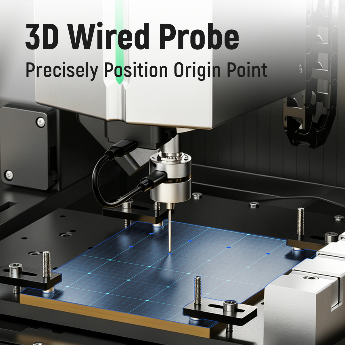
For the plaque maker, the immediate requirement might be placing lettering in the intended relationship to the blank. A workpiece-origin accessory addresses that locating need. For a different hypothetical project involving a fit-critical finished feature, the requirement includes demonstrating that the machined feature meets its specified limits. That calls for a suitable measurement method and an understanding of its uncertainty, not simply a successful probing response before cutting.
Neither task invalidates the other. Reliable location can be valuable without being a complete dimensional inspection, and inspecting a finished part does not replace establishing a useful machining reference. Keep the evidence attached to the output it actually evaluates.
When physical setup or checks are needed, follow the exact machine and probe procedures, keep the spindle stopped for hands-on adjustments, secure the stock and use the prescribed safe isolation. A generic specification is not an operating procedure, and another probe's speed, force or calibration instructions do not supply one.
Use repeatability evidence to understand consistency under its stated conditions. Use an appropriate reference comparison to evaluate the located result, and suitable inspection to evaluate a required finished feature. The useful probe choice is the one whose documented role serves the project—not the one whose smallest number has been stretched to answer every question.